Designing low reflectance touch screen displays for sunlight readability

Estimated reading time: 8 minutes
Introduction
This presentation, given during the 2017 Electronic Displays Conference, covers the impact of touch panel display integration on the system’s sunlight readability and methods manufacturers can utilize to produce low reflectance touch panels.
The below article was also published in EE World Online: https://www.eeworldonline.com/designing-low-reflectance-touch-panels-for-sunlight-readability/
What affects the sunlight readability of touch screen displays?

Placing a touch sensor on top of a display increases the overall reflectance of the device, which directly influences the readability of the display in bright conditions, especially outdoors on a sunny day. This doesn’t only impact mobile devices that are often used outdoors, but also automotive displays, ATMs, marine applications, navigational devices and many more.
This article outlines the relationship between the reflectance of a touch display system and its sunlight readability and explains the parameters that influence the reflectance. Different methods of how reflectance can be reduced will be discussed and compared in terms of effectiveness and cost.
Methods for achieving sunlight readability
For a display to be readable in an environment with very bright ambient light, the brightness of the display (i.e. the intensity of the light emitted by the display) needs to exceed the intensity of the light that is reflected on the display surface. In other words, if the intensity of the reflected light is close to the display´s brightness, the contrast of the display is reduced to a degree where the display’s readability is diminished to unacceptable levels. If the total reflectance is higher, the display will not be readable at all. In order to maintain readability, the display brightness needs to exceed the reflected light by a factor of at least 2.5. Military specifications require a factor of at least 4, some even 6.
The ambient brightness on a clear day in direct sunlight is about 6000 cd/m2, and the typical reflectance of a display system including a touch sensor without any special measures for reflectance reduction is about 14%. This means that the light reflected on such a surface would be 6000 x 0.14 = 780 cd/m2. Typical consumer type displays with a brightness of around 350 cd/m2 would not be readable under those conditions.
Adjusting the display brightness
One solution would be to boost up the display brightness to above 2000 cd/m2. Though possible in theory, this requires significantly more backlight LEDs (or other light sources) and/or higher driving current, leading to high power consumption, excessive heat dissipation, increased dimensions and shortened lifetime. This is unacceptable for mobile devices, but even for fixed applications or displays used in cars, the display brightness is usually limited to 1000 cd/m2 for the above-mentioned reasons.
Reducing the system reflectance
An alternative way to make these displays sunlight-readable is to reduce their reflectance to a level that ensures that the intensity of the reflected light remains significantly lower than the display brightness. Reducing only the surface reflectance is not enough because the incident light is not only reflected on the top surface. Underlying layers of different materials also contribute to the total reflection as light is also reflected at the interfaces of two different materials that have a different index of refraction. Therefore, adding a touch sensor to a display increases the total reflectance of the system.
Sources of Reflectance
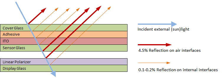
As mentioned above, without any reflection reduction measures the total reflectance of the touch display system is about 14%. As shown in figure (1), such a system comprises three glass/air interfaces: The top surface of the cover lens, the bottom surface of the sensor and the top surface of the display, each contributing approximately 4.5% to the total reflectance. There are also a few internal interfaces, however, those do not add significantly to the total reflectance as the refractive index of the materials those layers consist of (glass, ITO, adhesive) are quite similar to each other. Thus, reflectance reduction measures mainly focus on glass/air interfaces.
Methods for Reducing Reflectance
A. Reducing reflectance of top surface via AR films or coatings
The reflectance of the top surface can be reduced by either applying an AR-coating or laminating an AR-film, or any other type of film that has AR-properties and also serves an additional purpose (e.g. anti-glare, anti-smudge, anti-spall, polarization). The resulting top reflectance can be reduced to values between 1% and 2.5%, depending on the type of film used or, in case of AR-coatings, on the number of layers coated onto the surface. As one may expect, the lower the reflectance value of the film or coating the higher its cost.
B. Reducing reflectance of the airgap
The reflectance of the other two glass/air interfaces at the bottom of the sensor and on top of the display can be reduced by the four different methods outlined below. For easier comparability, the system reflectance values provided below are based on the assumption that no reflectance reduction measure is applied on the top surface.
1. Optical bonding
Optical bonding of the display and capacitive touch panel: This is achieved by filling the gap between the display and the sensor with a transparent adhesive. As a result, the two lower glass/air interfaces shown in figure (1) are eliminated which reduces the total reflectance to approximately 5%. Optical bonding, however, comes at a high price. It requires very specific types of liquid or film adhesives that are quite expensive, and the production yield of laminating two expensive components (the display and the touch sensor) contributes significantly to the total cost. For small to medium-sized displays (up to 12”), the estimated cost of optical bonding is about $1.00 per diagonal inch.
2. Top surface linear polarizer
Laminating a linear polarizer on the top surface: As the polarizer effectively allows only half of the sunlight to pass through, the intensity of the light reflected at all interfaces below this polarizer will also be reduced by half. This means that the portion of the reflectance that occurs below this surface decreases by about 50% from 9.5% to 4.75%, leading to an overall reflectance of around 9.25% when adding the surface reflectance. The main disadvantages of this solution are that (i) the surface is a film which is by far not as hard as a glass surface, (ii) the overall display brightness is reduced by the polarizer even though its polarization matches that of the display.
3. AR films and display polarizers
Laminating an AR-film on the bottom surface of the sensor and changing the display polarizer to a low reflectance version: This reduces the reflectance of each of the air/glass interfaces to below 2%, leading to an overall reflectance of about 8%. There are no specific disadvantages associated with this solution.
4. Top surface circular polarizer
Laminating a circular polarizer on the top surface: Light passing through a circular polarizer becomes circularly polarized. When such circularly polarized light is reflected on a surface, it changes the direction of polarization by 180 degrees and gets fully blocked by the top circular polarizer on its way back to the observer. This means, that any surface below the circular polarizer does not contribute to the total reflectance of the system anymore. Thus, only the top surface reflectance of 4.5% contributes to the overall surface reflectance. Apart from the high price of a circular polarizer, the main disadvantage is the impact on the viewing angle. Due to the mismatch of the linear display polarizer and the top circular polarizer, the display becomes invisible at certain viewing angles. This limitation is aggravated when viewing the display through polarized sunglasses.
Summary
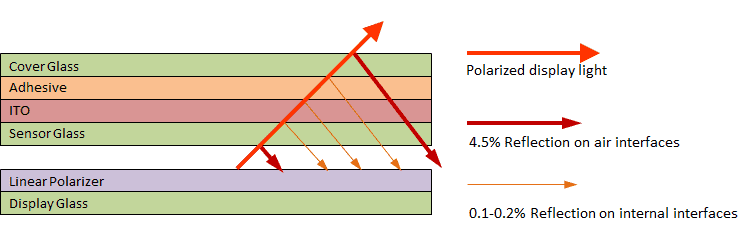
Similar to the way incident ambient light is reflected at the different interfaces, the light emitted by the display is reflected at the same interfaces at the same degree, as shown in figure (2). This results in a lower brightness at the top surface than on the display surface. Therefore, any reflectance reduction measures implemented to reduce ambient light reflectance also help to increase the effective brightness of a touch screen display system because a smaller portion of the display light is subject to total internal reflection.
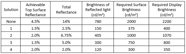
The below table shows the level of brightness a display must achieve when used in conjunction with a touch panel in order to be adequately readable in sunlight. These brightness values are provided for each of the four solutions outlined in section (B) when applied in combination with the surface reflection reduction described in section (A).